Difference between r1.6 and the current
@@ -14,9 +14,11 @@
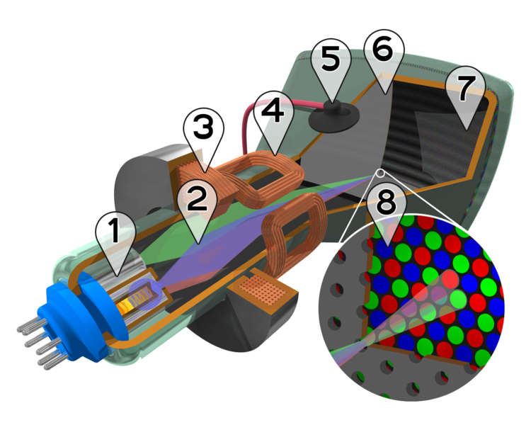
7. Phosphor layer with red, green, and blue zones8. Close-up of the phosphor-coated inner side of the screen
||[[Attachment(cathod-ray.gif,class="wikiLeft",width=400)]] ||
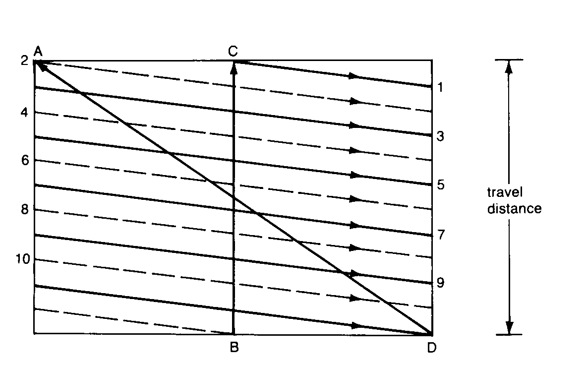
||Cathode ray beams filling the screen ||
||[[Attachment(television-line.gif,class="wikiLeft",width=400)]] ||
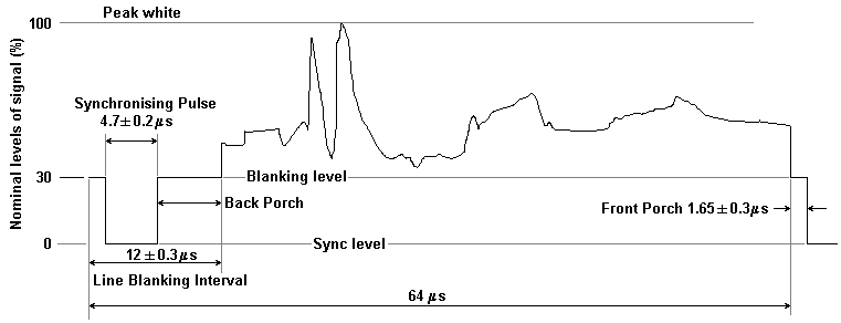
||One television line signals ||
from http://graffiti.virgin.net/ljmayes.mal/var/tvsync.htm[[Attachment(interlaced.gif,class="wikiLeft",caption="interlaced scan")]]
 [PNG image (331.65 KB)] |
| Braun cathode tube shooting one spot |
from . See also, http://members.chello.nl/~h.dijkstra19/page3.html
Cutaway rendering of a color CRT:
- Three Electron guns (for red, green, and blue phosphor dots)
- Electron beams
- Focusing coils
- Deflection coils
- Anode connection
- Mask for separating beams for red, green, and blue part of displayed image
- Phosphor layer with red, green, and blue zones
- Close-up of the phosphor-coated inner side of the screen
 [GIF image (12.75 KB)] |
| Cathode ray beams filling the screen |
 [GIF image (5.33 KB)] |
| One television line signals |
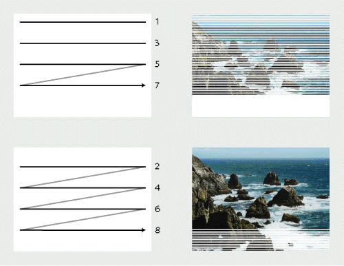
interlaced scan [GIF image (49.97 KB)]
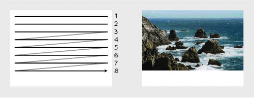
non-interlaced scan [GIF image (24.3 KB)]
from http://www.animotion.nl/dutch/anihow/interlaced.html


